From Transmitter to Receiver

Antennas
Correct answer: boom
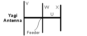
In a Yagi antenna:
The label “U” in the diagram refers to the long horizontal support structure, not one of the radiating elements.
Therefore, item U corresponds to the boom.
Last edited by jim.carroll. Register to edit
Tags: none
Correct answer: reflector
In a Yagi antenna:
In the diagram, V is the rear-most element, so it is the reflector.
Therefore, item V corresponds to the reflector.
Last edited by jim.carroll. Register to edit
Tags: none
Correct answer: director
In a Yagi antenna:
In the diagram, X is positioned in front of the driven element, so it is a director.
Therefore, item X corresponds to the director.
Last edited by jim.carroll. Register to edit
Tags: none
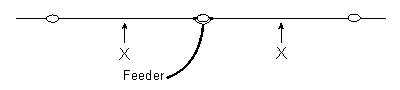
The antenna in this diagram has two equal lengths of wire shown as 'X' forming a dipole between insulators. The optimum operating frequency will be when the
Correct answer: length X+X is a little shorter than one-half of the signal wavelength
A centre-fed dipole antenna is normally designed to be approximately half a wavelength long at its operating frequency. In practice, the physical length must be made slightly shorter than \(\lambda/2\) because of end effects and the velocity factor of the wire, which cause the antenna to appear electrically longer than its physical length.
This shortening is typically a few percent, depending on wire diameter and construction.
Therefore, the optimum operating frequency occurs when the total length X + X is slightly shorter than one-half of the signal wavelength.
Last edited by jim.carroll. Register to edit
Tags: none
The antenna in this diagram can be made to operate on several bands if the following item is installed at the points shown at 'X' in each wire
Correct answer: D — a parallel-tuned trap
The diagram shows a dipole-style antenna with two insertion points marked "X" in each half of the wire, fed at the centre. This is a trap dipole. A parallel-tuned trap (a coil and capacitor wired in parallel) is inserted at each "X" position. At the trap's resonant frequency, it presents a very high impedance, effectively shortening the antenna electrically and isolating the outer sections. At lower frequencies the trap allows current to flow through into the outer sections, making the antenna appear longer. This lets a single antenna operate on two or more amateur bands.
Therefore, parallel-tuned traps inserted at the "X" points create the frequency-selective high-impedance barriers that allow a trap dipole to operate efficiently on multiple amateur bands.
Last edited by jim.carroll. Register to edit
Tags: none
The physical length of the antenna shown in this diagram can be shortened and the electrical length maintained, if one of the following items is added at the points shown at 'X' in each wire
Correct answer: A — an inductor
The diagram shows a centre-fed dipole antenna. The two "X" marks indicate points in each half of the dipole where a loading component is to be inserted. When a dipole is physically shorter than its resonant half-wavelength, it is electrically capacitive — the current and voltage are out of phase. Inserting an inductor (coil) at each marked point adds the missing inductive reactance, cancelling the capacitive reactance and restoring electrical resonance. This is called inductive loading, and the resulting antenna behaves as if it were the full resonant length even though it is physically shorter.
Therefore, inductive loading coils inserted at the "X" positions on each arm restore the electrical half-wave resonance of a physically shortened dipole antenna.
Last edited by jim.carroll. Register to edit
Tags: none
The approximate physical length of a half-wave antenna for a frequency of 1000 kHz is
Correct answer: 150 metres
Wavelength is related to frequency by:
\[ \lambda(\mathrm{m}) \approx \frac{300}{f(\mathrm{MHz})} \]
A frequency of 1000 kHz is:
\[ f = 1\ \mathrm{MHz} \]
So the wavelength is:
\[ \lambda = \frac{300}{1} = 300\ \mathrm{m} \]
A half-wave antenna has a physical length of approximately:
\[ \frac{\lambda}{2} = \frac{300}{2} = 150\ \mathrm{m} \]
In practice, the actual antenna may be slightly shorter due to end effects and velocity factor, but 150 metres is the correct approximate value.
Therefore, the approximate physical length of a half-wave antenna at 1000 kHz is 150 metres.
Last edited by jim.carroll. Register to edit
Tags: none
Correct answer: D — 12 metres
Wavelength and frequency are inversely related: as frequency increases, wavelength decreases. The standard formula uses the speed of light (approximately 300,000,000 m/s or 3 × 10⁸ m/s).
\[ \lambda = \frac{c}{f} \]
Given:
\[ \lambda = \frac{300{,}000{,}000}{25{,}000{,}000} = 12\ \mathrm{metres} \]
A quick mental shortcut: divide 300 by the frequency in MHz to get the wavelength in metres. 300 ÷ 25 = 12 m.
Therefore, the wavelength of a 25 MHz signal is 12 metres.
Last edited by jim.carroll. Register to edit
Tags: none
Magnetic and electric fields about an antenna are
Correct answer: C — perpendicular to each other
In any electromagnetic wave, the electric field (E-field) and the magnetic field (H-field) are always oriented at right angles (90°) to each other, and both are perpendicular to the direction of wave propagation. This relationship is a fundamental property of electromagnetic radiation and holds true regardless of antenna type, frequency, or time of day. Around a transmitting antenna, the near-field and far-field both exhibit this orthogonal relationship between the two field components.
Therefore, the electric and magnetic fields around an antenna are always perpendicular to each other, as required by the fundamental nature of electromagnetic wave propagation.
Last edited by jim.carroll. Register to edit
Tags: none
Radio wave polarisation is defined by the orientation of the radiated
Correct answer: B — electric field
Radio wave polarisation is defined by the orientation of the electric field component of the electromagnetic wave. For example, a vertical antenna produces a vertically polarised wave because its electric field oscillates in the vertical plane. The magnetic field is always perpendicular to the electric field, and it is the electric field's orientation that is used as the reference by convention.
Therefore, radio wave polarisation is always defined by the orientation of the electric field component of the radiated electromagnetic wave.
Last edited by jim.carroll. Register to edit
Tags: none
A half wave dipole antenna is normally fed at the point of
Correct answer: maximum current
A half-wave dipole antenna has a standing wave of current and voltage along its length. At the centre of the dipole:
This point provides a convenient feed impedance (typically around \(50\text{–}75\ \Omega\)), which matches common transmission lines and allows efficient power transfer.
At the ends of the dipole, the situation is reversed, voltage is maximum and current is near zero, which is why end-feeding is uncommon for a simple half-wave dipole.
Therefore, a half-wave dipole antenna is normally fed at the point of maximum current.
Last edited by jim.carroll. Register to edit
Tags: none
An important factor to consider when high angle radiation is desired from a horizontal half-wave antenna is the
Correct answer: height of the antenna
The radiation angle of a horizontal half-wave dipole is strongly influenced by its height above ground (in wavelengths).
Low height (e.g. < 0.5 λ):
Greater height:
Therefore, if high-angle radiation is desired, the key factor is the height of the antenna.
Therefore, the important factor is the height of the antenna.
Last edited by jim.carroll. Register to edit
Tags: none
An antenna which transmits equally well in all compass directions is a
Correct answer: B — quarterwave grounded vertical
A quarter-wave grounded vertical antenna radiates in all compass directions (azimuth) equally, making it omnidirectional in the horizontal plane. It works by using the ground (or a ground plane of radials) as an electrical mirror, producing a radiation pattern equivalent to a half-wave dipole stood on end. Because the antenna is vertical and symmetrical around its axis, signal strength is the same in every compass bearing.
Therefore, the quarter-wave grounded vertical is the correct choice for an antenna that transmits equally well in all compass directions.
Last edited by jim.carroll. Register to edit
Tags: none
A groundplane antenna emits a
Correct answer: vertically polarised wave
A groundplane antenna is essentially a vertical radiator mounted above a set of radial conductors that act as a reflective ground.
The electric field produced by a vertical radiator is oriented perpendicular to the earth’s surface, resulting in vertical polarisation of the transmitted radio wave.
Therefore, a groundplane antenna emits a vertically polarised wave.
Last edited by jim.carroll. Register to edit
Tags: none
The impedance at the feed point of a folded dipole antenna is approximately
Correct answer: 300 ohm
A folded dipole consists of two parallel conductors connected at both ends. Compared to a simple half-wave dipole (which has a feedpoint impedance of about \(75\ \Omega\)), the folded dipole increases the impedance by approximately the square of the number of conductors.
For a two-wire folded dipole:
\[ Z_{\text{in}} \approx 4 \times 75\ \Omega = 300\ \Omega \]
Therefore, the feedpoint impedance of a folded dipole is approximately 300 ohm.
Last edited by jim.carroll. Register to edit
Tags: none
The centre impedance of a 'half-wave' dipole in 'free space' is approximately
The feedpoint impedance of a half-wave dipole, installed about one wavelength or higher above ground (i.e. in "free space"), is 72 ohm. When the ends are lowered (i.e. into an "inverted V"), the impedance drops to around 50 ohms. The ends of the antenna should be insulated as they are high-voltage low-current points. The connections of the feedline to the antenna should be soldered because the centre of the dipole is a high-current low-voltage point.
Last edited by cmscouler. Register to edit
Tags: none
The effect of adding a series inductance to an antenna is to
Correct answer: decrease the resonant frequency
An antenna’s resonant frequency depends on its effective electrical length.
Adding a series inductance introduces additional inductive reactance, which electrically lengthens the antenna without increasing its physical length.
This lowers the frequency at which the antenna resonates.
Therefore, adding series inductance decreases the resonant frequency.
Last edited by jim.carroll. Register to edit
Tags: none
The purpose of a balun in a transmitting antenna system is to
Correct answer: D — match unbalanced and balanced transmission lines
A balun (contraction of balanced–unbalanced) is a device that interfaces an unbalanced transmission line (such as coaxial cable, where the outer shield is at ground potential) with a balanced load (such as a dipole antenna, where neither conductor is at ground). Without a balun, RF current can flow back down the outside of the coax braid, causing pattern distortion, increased interference, and feed-line radiation.
Baluns may be purely a current/choke type (suppressing common-mode currents) or a transformer type (also providing impedance transformation), but in either case their defining role is the balanced-to-unbalanced transition.
Therefore, the purpose of a balun in a transmitting antenna system is to match unbalanced and balanced transmission lines, ensuring correct current distribution on the antenna and preventing feed-line radiation.
Last edited by jim.carroll. Register to edit
Tags: none
A dummy antenna
Correct answer: D — duplicates the characteristics of an antenna without radiating signals
A dummy antenna (also called a dummy load) is a non-radiating resistive load that presents the same impedance to a transmitter as a real antenna would — typically 50 Ω. It allows a transmitter to be tested, tuned, or adjusted at full power without actually transmitting a signal over the air. The RF energy is safely dissipated as heat in the resistive element rather than being radiated.
Therefore, a dummy antenna duplicates the electrical characteristics of a real antenna — providing the correct impedance load — while preventing any signal from being radiated during transmitter testing or adjustment.
Last edited by jim.carroll. Register to edit
Tags: none
A half-wave antenna resonant at 7100 kHz is approximately this long
Correct answer: A — 20 metres
A half-wave dipole has a physical length of approximately half the wavelength of the operating frequency. The full wavelength at any frequency is found from the wave equation, and the half-wave length is then halved again (with a small shortening factor of about 5% applied in practice, but the approximation is sufficient here).
\[ \lambda = \frac{c}{f} \]
\[ \lambda = \frac{300{,}000\ \mathrm{km/s}}{7{,}100\ \mathrm{kHz}} = \frac{300\ \mathrm{m\cdot MHz}}{7.1\ \mathrm{MHz}} \approx 42.3\ \mathrm{m} \]
Half of that:
\[ \frac{42.3}{2} \approx 21.1\ \mathrm{m} \]
After applying the standard ~5% practical shortening factor, this comes to approximately 20 metres, consistent with operation on the 40-metre amateur band.
Therefore, a half-wave antenna resonant at 7100 kHz is approximately 20 metres long.
Last edited by jim.carroll. Register to edit
Tags: none
An antenna with 20 metres of wire each side of a centre insulator will be resonant at approximately
Correct answer: 3600 kHz
The antenna has 20 metres of wire on each side, so the total length is:
\[ L = 20 + 20 = 40\ \mathrm{m} \]
A simple half-wave dipole resonates when its total length is approximately half a wavelength:
\[ L \approx \frac{\lambda}{2} \]
So the wavelength is:
\[ \lambda \approx 2L = 80\ \mathrm{m} \]
Frequency and wavelength are related by:
\[ f(\mathrm{MHz}) \approx \frac{300}{\lambda(\mathrm{m})} \]
Substituting:
\[ f \approx \frac{300}{80} = 3.75\ \mathrm{MHz} \approx 3750\ \mathrm{kHz} \]
In practice, real antennas resonate slightly lower due to end effects and conductor diameter, so a value close to 3600 kHz is the best match.
Therefore, the antenna will be resonant at approximately 3600 kHz.
Last edited by jim.carroll. Register to edit
Tags: none
A half wave antenna cut for 7 MHz can be used on this band without change
Correct answer: 15 metre
A half wave antenna cut for 7 MHz has a fixed physical length equal to \(\lambda/2\) at that frequency. The same antenna will also be resonant at odd multiples of half wavelengths.
At 21 MHz (the 15 metre band), the wavelength is one third of the 7 MHz wavelength:
\[ \lambda_{21} = \frac{\lambda_{7}}{3} \]
The antenna length remains \(\lambda_{7}/2\), which becomes:
\[ \frac{\lambda_{7}}{2} = \frac{3\lambda_{21}}{2} = \frac{3\lambda}{2} \]
A \(3\lambda/2\) dipole is a resonant length, so the antenna can be used on the 15 metre band without changing its physical length.
Therefore, the same antenna length can be used without change on the 15 metre band.
Last edited by jim.carroll. Register to edit
Tags: none
This property of an antenna broadly defines the range of frequencies to which it will be effective
Correct answer: bandwidth
An antenna’s bandwidth is the range of frequencies over which it operates effectively, typically defined as the range where its performance (such as SWR or radiation efficiency) remains within acceptable limits.
This determines how wide a frequency range the antenna can cover without significant mismatch or loss.
Therefore, the property that broadly defines the effective frequency range of an antenna is its bandwidth.
Last edited by jim.carroll. Register to edit
Tags: none
The resonant frequency of an antenna may be increased by
Correct answer: A — shortening the radiating element
An antenna resonates when its physical length corresponds to a specific fraction of the operating wavelength (typically a half-wave or quarter-wave). Because wavelength and frequency are inversely related, a shorter antenna resonates at a higher frequency — just as a shorter guitar string produces a higher pitch.
\[ f = \frac{c}{\lambda} \]
where c is the speed of light (approximately 300,000,000 m/s) and λ is the wavelength. Reducing the physical length reduces the resonant wavelength, which raises the resonant frequency.
Therefore, shortening the radiating element is the correct way to increase an antenna's resonant frequency.
Last edited by jim.carroll. Register to edit
Tags: none
Insulators are used at the end of suspended antenna wires to
Correct answer: limit the electrical length of the antenna
End insulators are used to separate the active radiating portion of the antenna from its supporting ropes or structures.
Without an insulator, the supporting material (especially if damp or conductive) could become part of the antenna, effectively increasing its electrical length and altering its resonant frequency.
The insulator ensures that only the intended wire length contributes to radiation.
Therefore, end insulators are used to limit the electrical length of the antenna.
Last edited by jim.carroll. Register to edit
Tags: none
To lower the resonant frequency of an antenna, the operator should
Correct answer: A — lengthen the antenna
A resonant antenna's natural frequency is determined by its physical length. A half-wave dipole (or any resonant antenna) resonates when its length corresponds to a specific fraction of the wavelength of the operating frequency. Because wavelength and frequency are inversely related, making the antenna longer increases the wavelength it naturally resonates at, which means the resonant frequency decreases.
\[ f = \frac{c}{\lambda} \]
Where:
A longer antenna corresponds to a longer wavelength, and by the formula above, a longer wavelength means a lower resonant frequency.
Therefore, to lower an antenna's resonant frequency, the operator should lengthen the antenna so it resonates at a longer wavelength and correspondingly lower frequency.
Last edited by jim.carroll. Register to edit
Tags: none
Correct answer: dipole
A half-wave antenna consists of two equal conductive elements, each approximately:
\[ \frac{\lambda}{4} \]
forming a total length of:
\[ \frac{\lambda}{2} \]
This type of antenna is called a dipole.
Therefore, a half-wave antenna is called a dipole.
Last edited by jim.carroll. Register to edit
Tags: none
The resonant frequency of a dipole antenna is mainly determined by
Correct answer: its length
The resonant frequency of a dipole antenna is primarily determined by its physical length.
A half-wave dipole has a length approximately:
\[ L \approx \frac{\lambda}{2} \]
Since:
\[ f \approx \frac{300}{\lambda} \]
the antenna length directly sets the frequency at which it resonates.
Therefore, the resonant frequency is mainly determined by its length.
Last edited by jim.carroll. Register to edit
Tags: none
A transmitting antenna for 28 MHz for mounting on the roof of a car could be a
Correct answer: B — quarter wave vertical
A quarter wave vertical is the classic mobile HF antenna. At 28 MHz, a quarter wavelength is approximately 2.5 metres — a practical length for roof mounting. The car's metal roof acts as a ground plane, completing the antenna's electrical structure (effectively mirroring the antenna to create the equivalent of a half-wave dipole). This gives a low radiation angle and omnidirectional coverage, ideal for mobile operation.
\[ \lambda = \frac{300}{f(\text{MHz})} \]
\[ \frac{\lambda}{4} = \frac{300}{28 \times 4} \approx 2.68\ \mathrm{m} \]
Therefore, a quarter wave vertical with the car roof as ground plane is the correct and standard choice for a 28 MHz mobile antenna.
Last edited by jim.carroll. Register to edit
Tags: none
A vertical antenna which uses a flat conductive surface at its base is the
Correct answer: quarter wave ground plane
A vertical antenna that uses a flat conductive surface (real or simulated) at its base relies on that surface as a ground plane.
This configuration:
The antenna itself is typically:
\[ \frac{\lambda}{4} \]
in length.
Therefore, the antenna is a quarter wave ground plane.
Last edited by jim.carroll. Register to edit
Tags: none
The main characteristic of a vertical antenna is that it
Correct answer: C — receives signals from all points around it equally well
A vertical antenna is omnidirectional in the horizontal plane — it radiates and receives equally in all compass directions. This makes it particularly useful for mobile operation, local nets, and situations where the direction of the other station is unknown or variable. The radiation pattern forms a doughnut shape around the antenna, with maximum signal broadside (horizontally) and a null directly off the tip.
Therefore, the defining characteristic of a vertical antenna is its omnidirectional radiation pattern in the horizontal plane, receiving signals equally well from all directions around it.
Last edited by jim.carroll. Register to edit
Tags: none
At the ends of a half-wave dipole the
Correct answer: B — voltage is high and current is low
A half-wave dipole is a resonant antenna exactly half a wavelength long. At resonance, standing waves form along the element. The current distribution follows a sine-wave pattern, reaching a maximum (antinode) at the centre of the dipole and falling to zero at the open ends. Voltage behaves oppositely — it is at a minimum (node) at the feed point centre and rises to a maximum at the tips. This is the same behaviour seen at the open end of any resonant transmission line: high voltage, low current.
The relationship is complementary: wherever current is at a peak, voltage is at a null, and wherever voltage is at a peak, current is at a null.
Therefore, at the ends of a half-wave dipole the voltage is at its maximum and the current is at its minimum (effectively zero).
Last edited by jim.carroll. Register to edit
Tags: none
An antenna type commonly used on HF is the
Correct answer: cubical quad
The cubical quad is a commonly used directional antenna on HF bands.
It consists of one or more wire loops supported by a frame and is practical to construct at HF wavelengths.
Therefore, an antenna commonly used on HF is the cubical quad.
Last edited by jim.carroll. Register to edit
Tags: none
A Yagi antenna is said to have a power gain over a dipole antenna for the same frequency band because
Correct answer: C — it concentrates the radiation in one direction
A Yagi antenna achieves gain over a dipole not by generating extra power, but by focusing the available transmit power into a narrower beam in one direction. This directivity is produced by the interaction between the driven element and the parasitic elements — the reflector (slightly longer, placed behind the driven element) and one or more directors (slightly shorter, placed in front). Energy that would otherwise radiate in all directions is instead reinforced in the forward direction and suppressed elsewhere, producing a net gain compared to a dipole radiating equally to the front and rear.
Therefore, a Yagi's power gain over a dipole results from concentrating radiated energy in one direction rather than creating additional power.
Last edited by jim.carroll. Register to edit
Tags: none
The maximum radiation from a three element Yagi antenna is
Correct answer: in the direction of the director end of the boom
In a Yagi antenna:
The reflector pushes energy forward, while the directors focus and guide it in that same direction.
This results in:
maximum radiation toward the director end
reduced radiation toward the reflector (good front-to-back ratio)
It is not strongest toward the reflector.
Radiation is not at right angles to the boom.
The feeder direction is unrelated.
Therefore, maximum radiation is in the direction of the director end of the boom.
Last edited by jim.carroll. Register to edit
Tags: none
The reflector and director(s) in a Yagi antenna are called
Correct answer: parasitic elements
In a Yagi-Uda antenna, only one element (the driven element) is directly connected to the feedline.
The other elements:
are not electrically connected to the transmitter or receiver. Instead, they are excited by the electromagnetic field radiated by the driven element.
These elements re-radiate energy due to induced currents, and their lengths are chosen to:
This improves:
Because they are not directly driven but interact with the radiated field, they are known as parasitic elements.
Therefore, the reflector and directors in a Yagi antenna are called parasitic elements.
Last edited by jim.carroll. Register to edit
Tags: none
An isotropic antenna is a
Correct answer: hypothetical point source
An isotropic antenna is a theoretical reference antenna that radiates equally in all directions in three-dimensional space.
It is considered a point source with no preferred direction of radiation, producing a perfectly spherical radiation pattern. This makes it useful as a standard reference when comparing antenna gain.
Therefore, an isotropic antenna is a hypothetical point source.
Last edited by jim.carroll. Register to edit
Tags: none
The main reason why many VHF base and mobile antennas in amateur use are 5/8 of a wavelength long is that
Correct answer: most of the energy is radiated at a low angle
A 5/8 wavelength vertical antenna is commonly used on VHF because its radiation pattern concentrates more energy at low elevation angles compared with a quarter-wave antenna.
Low-angle radiation is desirable for VHF base and mobile operation because it:
Although a 5/8 λ antenna has a more complex feed impedance and usually requires matching, its radiation efficiency at low angles makes it very popular for VHF work.
Therefore, many VHF base and mobile antennas are 5/8 wavelength long because most of the energy is radiated at a low angle.
Last edited by jim.carroll. Register to edit
Tags: none
A more important consideration when selecting an antenna for working stations at great distances is
Correct answer: B — angle of radiation
When working stations at great distances (DX), the most critical antenna characteristic is its angle of radiation — the angle above the horizon at which the antenna launches most of its energy into the sky. For long-distance HF propagation, a low angle of radiation is needed so the signal reaches the ionosphere at a shallow angle, allowing it to refract back to earth at a distant point. High-angle radiation tends to return to earth much closer to the transmitter (or skip overhead entirely for very long paths).
Therefore, for working distant stations, selecting an antenna with a low angle of radiation is far more important than any other listed factor.
Last edited by jim.carroll. Register to edit
Tags: none
On VHF and UHF bands, polarisation of the receiving antenna is important in relation to the transmitting antenna, but on HF it is relatively unimportant because
Correct answer: the ionosphere can change the polarisation of the signal from moment to moment
On HF, most long-distance communication occurs via skywave propagation through the ionosphere.
As radio waves pass through the ionised layers, their polarisation can be altered due to:
This means the received signal’s polarisation may vary continuously, regardless of the transmitting antenna’s original polarisation.
Therefore, on HF the ionosphere can change the signal’s polarisation from moment to moment.
Last edited by jim.carroll. Register to edit
Tags: none