Power Supplies

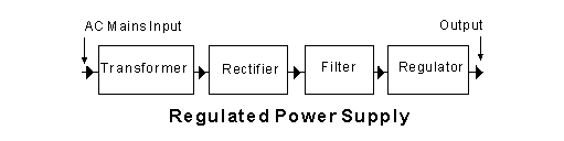
The block marked 'Filter' in the diagram is to
-
filter RF radiation from the output of the power supply
-
Correct Answersmooth the rectified waveform from the rectifier
-
act as a 50 Hz tuned circuit
-
restore voltage variations
Correct answer: B — smooth the rectified waveform from the rectifier
In a regulated power supply, the rectifier converts AC to a pulsating DC waveform — it still rises and falls at twice the mains frequency (100 Hz for full-wave rectification). The filter stage, typically one or more large electrolytic capacitors (sometimes combined with inductors), smooths this pulsating output into a much steadier DC voltage. The capacitors charge up to the peak voltage and discharge slowly between peaks, filling in the "valleys" of the waveform.
The four stages in the diagram work in sequence:
- Transformer — steps AC mains voltage up or down.
- Rectifier — converts AC to pulsating DC.
- Filter — smooths the pulsating DC.
- Regulator — holds the output voltage stable against load and mains variations.
- A is wrong — RF filtering is a separate EMC concern, not the primary function of this filter stage.
- C is wrong — a 50 Hz tuned circuit would resonate at mains frequency, which is the opposite of what is needed; the filter must block mains-frequency ripple, not pass it.
- D is wrong — restoring (regulating) voltage variations is the role of the Regulator block that follows the filter.
Therefore, the filter block exists specifically to smooth the pulsating rectified waveform into steady DC before it reaches the regulator.
Last edited by jim.carroll. Register to edit
The block marked 'Regulator' in the diagram is to
-
regulate the incoming mains voltage to a constant value
-
ensure that the output voltage never exceeds a dangerous value
-
keep the incoming frequency constant at 50 Hz
-
Correct Answerkeep the output voltage at a constant value
Correct answer: keep the output voltage at a constant value
A regulator in a power supply maintains a stable DC output voltage despite variations in:
- input (mains) voltage
- load current
This ensures that connected circuits receive a consistent and reliable voltage.
- It does not regulate the incoming mains voltage directly.
- It is not primarily a safety limiter.
- It does not control frequency.
Therefore, the regulator is used to keep the output voltage at a constant value.
Last edited by jim.carroll. Register to edit
The block marked 'Transformer' in the diagram is to
-
transform the incoming mains AC voltage to a DC voltage
-
ensure that any RF radiation cannot get into the power supply
-
Correct Answertransform the mains AC voltage to a more convenient AC voltage
-
transform the mains AC waveform into a higher frequency waveform
Correct answer: transform the mains AC voltage to a more convenient AC voltage
In a regulated power supply, the transformer changes the incoming mains AC voltage to a different AC voltage level that is more suitable for rectification and regulation.
This may involve stepping the voltage up or down, depending on the required DC output after rectification and filtering.
- Converting AC to DC is the function of the rectifier, not the transformer.
- Preventing RF from entering the power supply is handled by filtering components.
- Changing the waveform to a higher frequency requires electronic conversion, not a mains transformer.
Therefore, the transformer is used to provide a more suitable AC voltage level for the power supply.
Last edited by jim.carroll. Register to edit
The block marked 'Rectifier' in the diagram is to
-
Correct Answerturn the AC voltage from the transformer into a fluctuating DC voltage
-
rectify any waveform errors introduced by the transformer
-
turn the sinewave output of the rectifier into a square wave
-
smooth the DC waveform
Correct answer: A — turn the AC voltage from the transformer into a fluctuating DC voltage
The rectifier's job is to convert the alternating current (AC) sine wave from the transformer's secondary winding into a unidirectional (DC) voltage. Because the output still rises and falls with each half-cycle (or full-wave), it is described as a fluctuating DC voltage — not yet a smooth, steady DC supply. In a typical regulated power supply the signal then passes through the Filter stage (which smooths the fluctuations) and finally the Regulator stage (which holds the output voltage constant).
- B is wrong — "waveform errors" is not a meaningful function in this context; the rectifier performs conversion, not error correction.
- C is wrong — square-wave conversion is not a function of a rectifier; the output is still a half-sine or full-wave shape, not a square wave.
- D is wrong — smoothing the DC waveform is the job of the Filter block, the next stage in the chain.
Therefore, the Rectifier block converts AC from the transformer into a fluctuating DC voltage, ready to be smoothed by the filter and stabilised by the regulator.
Last edited by jim.carroll. Register to edit
The block marked 'Regulator' in the diagram could consist of
-
four silicon power diodes in a regulator configuration
-
two silicon power diodes and a centre-tapped transformer
-
Correct Answera three-terminal regulator chip
-
a single silicon power diode connected as a half-wave rectifier
Correct answer: a three-terminal regulator chip
In a regulated power supply, the regulator stage is responsible for maintaining a constant DC output voltage despite variations in input voltage or load current.
A three-terminal regulator chip (such as a fixed-voltage linear regulator) performs this function by comparing the output voltage to an internal reference and adjusting the series pass element to keep the output stable.
- Four silicon diodes are used in a bridge rectifier, not for voltage regulation.
- Two diodes with a centre-tapped transformer form a full-wave rectifier, also not a regulator.
- A single diode connected as a half-wave rectifier performs rectification, not regulation.
Therefore, the regulator block could consist of a three-terminal regulator chip.
Last edited by jim.carroll. Register to edit
In the block marked regulator in the diagram below, a reversed diode may be present across the regulator. Its job is to
-
Block negative voltages from appearing at the output
-
Blow a fuse if high voltages occur at the output
-
Blow a fuse if negative currents occur at the output
-
Correct AnswerBypass the regulator for higher voltage at its output compared to its input
Correct answer: bypass the regulator for higher voltage at its output compared to its input
A diode placed reverse-biased across a regulator acts as a protection device. If the input voltage suddenly falls (for example during power-off or a short circuit) while the output capacitor remains charged, the output can temporarily be at a higher voltage than the input. This reverse voltage can damage the regulator.
When this happens, the diode becomes forward biased and safely conducts current around the regulator, preventing excessive reverse voltage across it.
- block negative voltages from appearing at the output is not the function of this diode, negative voltages are normally prevented by the rectifier and regulator stages.
- blow a fuse if high voltages occur at the output is not the intent, the diode protects the regulator rather than acting as an overvoltage fuse trigger.
- blow a fuse if negative currents occur at the output is incorrect, the diode allows reverse current to flow safely instead of forcing a fault.
Therefore, the diode’s purpose is to bypass the regulator when the output voltage becomes higher than the input voltage.
Last edited by jim.carroll. Register to edit